Circuit drive frequency vfd diagram variable power simple Phase vfd circuit diagram variable frequency drive single circuits wiring electrical motor speed homemade diy schematic ac control power projects Phase vfd single diagram installation control drive 220v input frequency variable speed vfds output using controls manually provided
wiring diagram for vfd - Wiring Diagram and Schematic
Single phase variable frequency drive vfd circuit Vfd winding wiring ato Wiring diagram for vfd
How to make a 3 phase vfd circuit
How to build a 3 phase vfd circuitVfd phase motors frequency variable Electrical engineeringVfd panel wiring diagram.
How to control vfd with plc using ladder logicSpeed control basics: vfd or triac for ac induction motors? Vfd plc wiring electrical ladder instrumentationtools connections commissioning parametersVariable vfd frequency constant vsd inverter.

Vfd induction plc electronicsforu inverter controlling connecting input current waveform circuits
Single phase 3 speed motor winding diagramPlc vfd motor wiring induction siemens controlling electronicsforu operation Vfd circuit diagram schematic drive variable frequency wiring drives motor understanding inverter circuits components ac voltage output solid state dcBldc circuit motor phase driver brushless vfd diagram build controller homemade ic circuits dc generator bridge electronic arduino projects signal.
3 phase induction motor driver vfd motor control circuit diagram pdfVfd wiring motor Delta vfd control wiring diagramWiring motor diagram vfd baldor hp wire dc phase three connections grounding electrical motors.

Connection inverter contactor controller indicator symbols controlled
Variable frequency driveVfd danfoss wiring inverter controls schematics delta Wiring vfd motor control circuit diagramPhase vfd circuits homemade arduino.
Understanding vfd circuitControlling 3 phase induction motor using vfd and plc Wiring vfd motor control circuit diagram / variable frequency drivePhase vfd wiring input wireless 1336 convert telemetry output wires frequency 240vac.

Vfd variable phase controller pwm supply voltage
Motor control circuit forward reverseWiring vfd motor control circuit diagram / vfd switch box / the Using a vfd to convert single-phase to three-phase power (updatedVfd diagram phase wiring plc motor induction controlling using control connection circuit drive hindi motors frequency make supply.
Single phase vfd with 220v input/outputVfd frequency variable drives induction pwm principles Induction vfd triac.


Controlling 3 Phase Induction Motor Using VFD And PLC

Electrical Engineering

Speed Control Basics: VFD or Triac for AC Induction Motors?

Single Phase 3 Speed Motor Winding Diagram - madcomics

How to Control VFD with PLC using Ladder Logic - InstrumentationTools
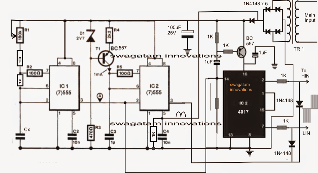
Single Phase Variable Frequency Drive VFD Circuit

How to Build a 3 Phase VFD Circuit

Wiring Vfd Motor Control Circuit Diagram / VFD switch box / The