Rectifier wave half circuit working characteristics using diode principle positive cycle voltage load input Rectifier capacitor Half wave rectifier with a capacitor filter and ripple factor calculation
Rectifier Circuit Diagram | Half Wave, Full Wave, Bridge - ETechnoG
Wave rectifier circuit Rectifier circuit wave half diagram parameters explanation application working figure1 What are half-wave rectifiers? definition, circuit and working of half
Rectifier wave half positive engineering stack
Half wave rectifier – circuit diagram, theory & applicationsHalf wave rectifier What is half wave and full wave rectifier?Rectifier wave half diagram circuit capacitor factor ripple filter calculation diode load halfwave together.
Circuit rectifier wave half diagram seekic electrical shown belowHalf-wave rectifier circuit Single phase half wave rectifier- circuit diagram,theory & applicationsHalf wave rectifier: principle & working.

Wave half rectifier filter capacitor rectifiers formula circuit diagram dc using electrical4u pulsating capacitive
Single phase half wave controlled rectifier with rl loadBuild a fast half-wave rectifier circuit diagram Half wave rectifier circuit explanation: working, parameters andHalf wave rectifier schematic diagram.
Wave half rectifier diode ac supply voltage output peak circuit inverse operation dc value load average input rectification piv signalOperational amplifier Rectifier waveform inputRectifier circuit half wave diagram fast build forget don if click.

Rectifier half diode breadboard circuitdigest diodes
Half wave rectifierRectifier transformer waveform tapped etechnog Rectifier half phase controlled rl currentWave rectifier half circuit diagram hwr.
Rectifier circuit applicationsHalf wave and full wave precision rectifier circuit using op-amp Rectifier diode voltage rectification diodes operation supply zener regulator detectorSingle phase half wave rectifier- circuit diagram,theory & applications.

Wave half rectifier diagram circuit working principle
Rectifier circuit diagramRectifier circuit diagram Rectifier diode reasoning amplifier operation operational cycleHalf wave rectifier – circuit diagram, theory & applications.
Half wave rectifier principleDraw the circuit diagram of a half wave rectifier and explain its Rectifier half circuit wave phase single diagram try learn looksHalf wave rectifier – definition, working, circuit diagram, theory.

Solved half wave rectifier circuit (vin,vout,vf)
Design of half wave rectifier circuit [single phase]Half wave rectifier by sravani annapurna.a(221710303057) Half wave rectifier circuit working and characteristicsWave half rectifier circuit diagram rectifiers working electrical4u voltage principle ac output process ll through go now.
☑ full wave half wave rectifier circuit diagramHalf wave rectifier ☑ filter capacitor formula for half wave rectifierRectifier working explain shaalaa diode junction.

Rectifier wave half working diode gif rectification operation animation principle engineering tutorial connected engineeringtutorial figure
Wave half circuit rectifier diagram rectifiers working represents below figureCircuit wave rectifier half diagram waveforms principle working Rectifier wave half circuit vout vin vf show problem figured im has solved clearly work but confused been shown.
.


☑ Full Wave Half Wave Rectifier Circuit Diagram
HALF WAVE RECTIFIER BY SRAVANI ANNAPURNA.A(221710303057)

☑ Filter Capacitor Formula For Half Wave Rectifier

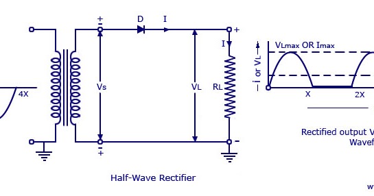
Half Wave Rectifier Circuit Working and Characteristics

Half Wave Rectifier Circuit Explanation: Working, Parameters and

Half Wave Rectifier - Circuit Diagram and Working Principle, » ElectroDuino